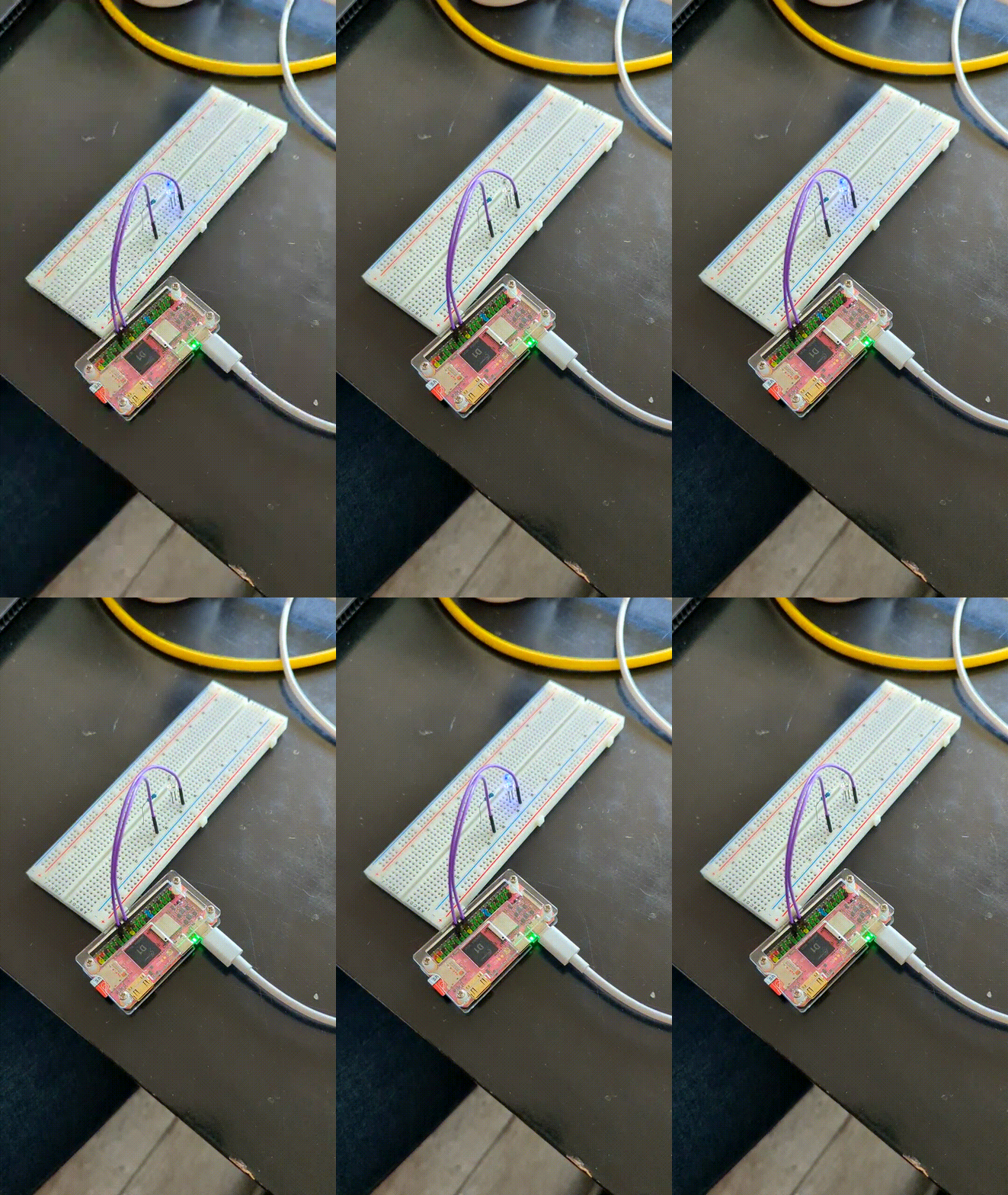
GPIO on the MangoPi MQ-Pro
One of the last aspects I wanted to explore and get working on my MangoPi MQ-Pro, is GPIO. For this experiment, like my previous endeavor trying out Bluetooth on my MangoPi MQ-Pro, I used the Ubuntu 22.10 RISC-V image for the SiPeed LicheeRV Dock image.
No extra configuration is needed to get GPIO working with this image on the MangoPi MQ-Pro. I tried out three different ways of accessing the GPIO pins; using legacy sysfs-based access, using the userspace GPIO driver, and lastly using lgpio from Python.

Phyiscal connection
First of all, I physically connected a LED to the GPIO pins of my MangoPi MQ-Pro. I connected a blue LED to pin 18 of the GPIO array, with a 1k resistor between it.
Legacy sysfs-based access
To use the sysfs-based approach to access the GPIO pins, you first need to find out the pin numbers the MangoPi MQ-Pro uses internally. This is a mapping table for this:
| GPIO | Pin | Pin | GPIO |
|---|---|---|---|
| 1 | 2 | ||
| 205 | 3 | 4 | |
| 204 | 5 | 6 | |
| 39 | 7 | 8 | 40 |
| 9 | 10 | 41 | |
| 117 | 11 | 12 | 37 |
| 118 | 13 | 14 | |
| 32 | 15 | 16 | 33 |
| 17 | 18 | 110 | |
| 19 | 20 | ||
| 21 | 22 | 65 | |
| 23 | 24 | ||
| 25 | 26 | 111 | |
| 145 | 27 | 28 | 144 |
| 42 | 29 | 30 | |
| 43 | 31 | 32 | 64 |
| 44 | 33 | 34 | |
| 38 | 35 | 36 | 34 |
| 113 | 37 | 38 | 35 |
| 39 | 40 | 36 |
So, if you have connected an output (LED) to pin 18, we need to access this using pin 110. With the following command we can start interacting with this exact pin, these will have to be ran as root:
# echo 110 > /sys/class/gpio/export
# echo out > /sys/class/gpio/gpio110/direction
# cat /sys/class/gpio/gpio110/direction
To make the LED light up, you can execute this command:
# echo 1 > /sys/class/gpio/gpio110/value
And to turn it off again:
# echo 0 > /sys/class/gpio/gpio110/value
When you’re done playing around, you can remove the resources to this pin:
# echo 110 > /sys/class/gpio/unexport
To make the LED blink, you can create a simple script:
while true
do
        echo 0 > /sys/class/gpio/gpio110/value
        sleep 1
        echo 1 > /sys/class/gpio/gpio110/value
        sleep 1
done
Userspace GPIO driver
To make the same LED turn on as in the previous step, you can execute:
# gpioset gpiochip0 110=1
And to turn if off again:
# gpioset gpiochip0 110=0
And a script to make it blink:
while true
do
        gpioset gpiochip0 110=0
        sleep 1
        gpioset gpiochip0 110=1
        sleep 1
done
Lgpio from Python
To use the GPIO pins from Python, we will have to install a package:
# apt update
# apt install python3-lgpio
You can create a script name blink.py to make the GPIO pin blink:
import time
import lgpio

LED = 110

# open the gpio chip and set the LED pin as output
h = lgpio.gpiochip_open(0)
lgpio.gpio_claim_output(h, LED)

try:
    while True:
        # Turn the GPIO pin on
        lgpio.gpio_write(h, LED, 1)
        time.sleep(1)

        # Turn the GPIO pin off
        lgpio.gpio_write(h, LED, 0)
        time.sleep(1)
except KeyboardInterrupt:
    lgpio.gpio_write(h, LED, 0)
    lgpio.gpiochip_close(h)
When executing the script by executing python3 blink.py, the LED should blink.